
Broaching
|
Broaching |
Broaching is a machining process based on the use of a broaching tool ( shape tool) mounted on a broaching machine or any other specific machine.
It is possible to perform broaching on any machine that allows axial traction or thrust: press, planer, mortising machine, shaper and possibly on turn.
The principle is to remove the material along a slot in a strict direction, between the part and the stock, extending it to the limits of the geometry.
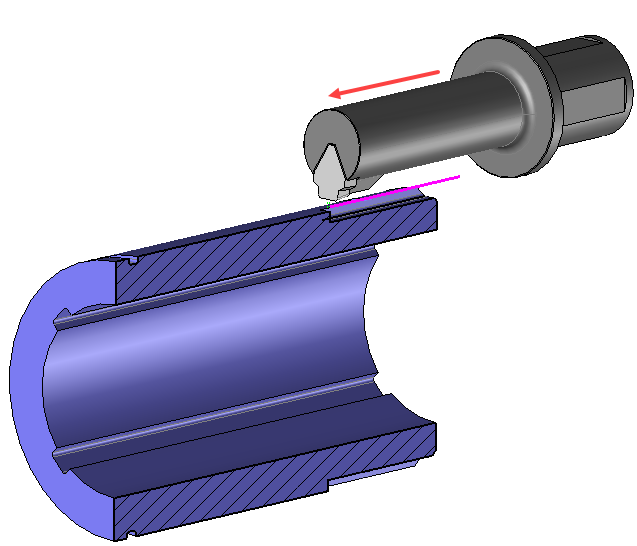
 As this machining is specific, it is mainly performed using the shape of the tool.
The topological analysis engine analyzes the selected geometry to check if the generation of the tool path is possible.
If the geometry is conform the algorithm after calculation will automatically generate the tool paths in the center of the selected face, in the longitudinal direction, while taking into account the material height in order to generate a sufficient number of radial passes.
This type of operation mostly involves plunges outside material, manual or automatic overlength options are available to extend the path at entry or exit.
External  or internal
  broaching is possible.
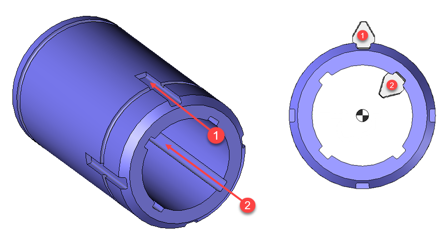
Simply select the bottom of the slots so that the topological analysis recognizes the area to be machined.
The stock management in the broaching function automatically determines the height of the material to be machined in the slot and also allows the paths along the slot to be optimized according to the stock existing at each radial pass.
It is also possible to manually set the broaching operation by selecting a profile (1).
The face normal (2) and the machining direction (3) must be indicated.
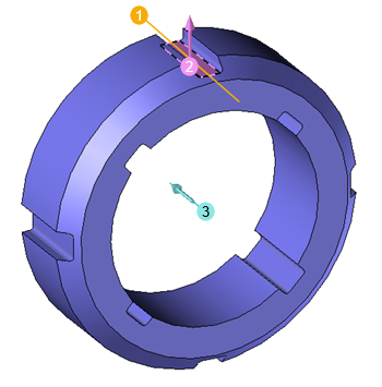
When machining on a sketch, just define its position in relation to the area to be machined:
In the example above the sketch is positioned in the center and at the bottom of the slot, but the user can choose whether he wants to machine to the left or right of the profile.
It is also possible to define whether the sketch is above the slot or at the bottom.
The position parameters are only available for machining on a sketch, if the selected geometry is directly on the bottom face of the slot the topology of the part is used, so these positioning options are grayed out.
It is then possible to modify values by opening one of the icons on the left.
|
Select Favorite
Instead of modifying n values, this option allows you to restore (or save) values that have already been entered.
|
|
Select the tool to use
By default, if the previous operation tool can be used, it is reused for this operation (the name of the tool appears in the graphic area next to
If the previous tool is not suitable or if this is the first operation, you must select a tool to validate the operation (
|
|
Define Cutting Conditions for Operation
Use this icon to modify the cutting conditions of the current operation.
|
|
Define or Add Geometries to Machine
Use this icon to select (or remove) machinable geometries. This geometry is automatically added, by first selecting the geometry and right-clicking "End Milling". You do not have to access the icon to do this.
Define Milling Boundaries
You can also apply trims (XYZ or contour) to the current operation.
|
|
Define all milling settings
Each milling has specific settings. Use this icon to access all settings (such as stocks to leave, altitudes, plunge modes, milling modes, etc.)
|
|
Define ISO File Settings
Use this icon to define which comment to use for the ISO code or to decide which inclined plane matrices to use.
|
|
Define colinear axis
This icon is available only if the current machine has colinear axis.With this icon it will then be possible to choose the axis drives by the operation.We also can choose the Z value of the fix axis.
|
|
Define Operation Properties
Use this icon to define whether you would like to update the stock or calculate the result later.
|
|
Confirm
To confirm the current operation, pressing this icon to right-click outside the window and use the "OK" menu
|
|
Cancel
If you wish to cancel the operation, click this icon.
|
|
Preview
Display or hide the machining area. When this is hidden, this area is not calculated, and response times improve.
|
|
Show Label
Allows you to display or hide the graphic area label.
|
|
Editing Update
Each time a setting is changed (such as the axial depth), all calculations for updating the hatching area and the trajectory are triggered. The setting change may take a few moments. In several cases, settings must be modified before updating the calculations. For this, press this icon. In the case, the hatching area and trajectory (for example) are not recalculated before pressing this icon again.
|


 )
) )
)


