![]()
Breaking Edges
|
Breaking Edges |
Automatically complete chamfers (not on the part) on some or all sharp edges on the milled part.
This function also allows you to automatically mill the chamfers drawn on the geometric model.
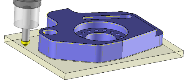
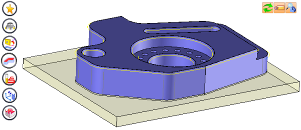
To select the edges to mill from the Geometry window, entities to mill must be included in the list of geometries. To do this, have TopSolid'Cam automatically detect the sharp edges of the part on which angles will be broken or indicate this manually. They appear on the part and are added to the list of geometries, you can therefore delete geometries or add them in the form of sketches.
You can also search chamfers on the part that will be milled using the breaking edges function if its flat dimensions are less than those defined in the breaking angles function.
From the 2D/3D menu or using the mouse (right-click), select Other / Breaking Edges.
An icon bar appears to the left of the screen. There are no labels available for this function.
 it is essential to define the geometry on which the angles must be broken:
Enabling certain generation settings allows you to filter the automatic selection.
you can:
Search for chamfers on the part.
Remove the selection of cylinders of which the diameter is less than a value.
Remove the selection of cylinders of which the length is less than a value.
to remove edges under a defined altitude from the selection.
You can select whether to use automatic search when you click the edges of the part or a previously created sketch.
|
Select Favorite
Instead of modifying n values, this option allows you to restore (or save) values that have already been entered.
|
|
Select the tool to use
By default, if the previous operation tool can be used, it is reused for this operation (the name of the tool appears in the graphic area next to
If the previous tool is not suitable or if this is the first operation, you must select a tool to validate the operation (
|
|
Define Cutting Conditions for Operation
Use this icon to modify the cutting conditions of the current operation.
|
|
Define or Add Geometries to Machine
Use this icon to select (or remove) machinable geometries. This geometry is automatically added, by first selecting the geometry and right-clicking "End Milling". You do not have to access the icon to do this.
Define Milling Boundaries
You can also apply trims (XYZ or contour) to the current operation.
|
|
Define All Milling Settings
Each milling has specific settings. Use this icon to access all settings (such as stocks to leave, altitudes, plunge modes, milling modes, etc.)
|
|
Define ISO File Settings
Use this icon to define which comment to use for the ISO code or to decide which inclined plane matrices to use.
|
|
Define colinear axis
This icon is available only if the current machine has colinear axis.With this icon it will then be possible to choose the axis drives by the operation.We also can choose the Z value of the fix axis.
|
|
Define Operation Properties
Use this icon to define whether you would like to update the stock or calculate the result later.
|
|
Confirm
To confirm the current operation, pressing this icon to right-click outside the window and use the "OK" menu
|
|
Cancel
If you wish to cancel the operation, click this icon.
|
|
Preview
Display or hide the machining area. When this is hidden, this area is not calculated, and response times improve.
|
|
Show Label
Allows you to display or hide the graphic area label.
|
|
Editing Update
Each time a setting is changed (such as the axial depth), all calculations for updating the hatching area and the trajectory are triggered. The setting change may take a few moments. In several cases, settings must be modified before updating the calculations. For this, press this icon. In the case, the hatching area and trajectory (for example) are not recalculated before pressing this icon again.
|
 Visibility management when editing the operation: click on the icons below
Machine visibility |
WCS visibility |
Tool visibility |
Collision visibility |
Stock and finish visibility |
Tool paths visibility |
|
|
|
|
|
|
|
|


 )
) )
)


