
3D Sweeping
|
3D Sweeping |
Icon Access: 
Location: 2D/3D\3D Sweeping
Development:
Create the machining tool path of a tool by completely or partially "sweeping" the face.
Three kind of sweeping operation exist
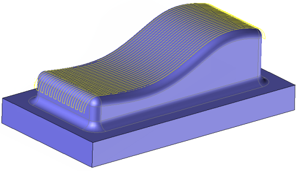
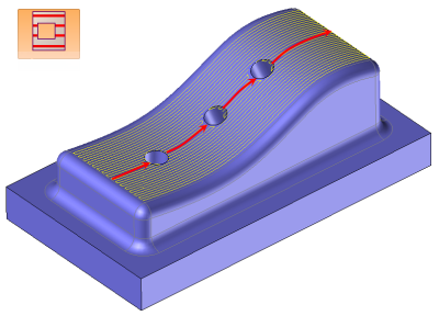
 The classic sweeping:
It allows or totally machine a face or a set of adjacent faces in 3,4 or 5 axis.
The machining direction is linlked to the parametrics curves of the faces to machine.
Milling can be limited by parametric values and/or other adjacent faces.
 |
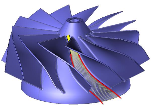
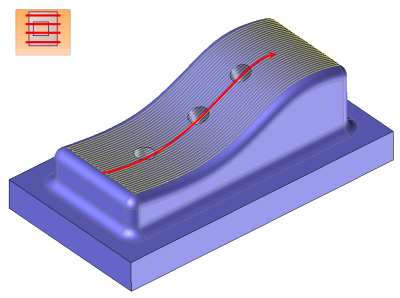
 Sweeping between two curves:
It allows to completly machine or not a face in 3,4 or 5 axis
First select a face and then two open or close curves
The machining direction is linked the the selected curves.
The tool path is limited between the two curves.
 |
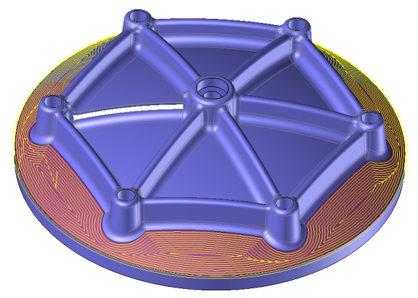
 Pocketing between curves:
it allows to completly machine or not a face by making a pocketing in 3,4 or 5 axis mode.
Simply select a face then one or two closed curves between which we want to make the operation.
If no curve has been selected the operation is automatically trimmed to the face.
 It is often advice to use the trimmed mode
  to avoid collisions....
 |
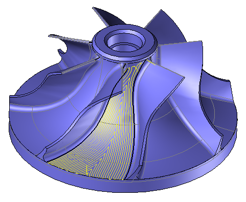
 The fishbone
It allows to completly machine or not a face in 3,4 or 5 axes.
Just select first a face and then two open or close curves
The sweeping « fishbone » consists in realizing parallel profiles to the initial curves by limiting them reciprocally when they intersect and bringing them together to from one profil for each step over value.
The machining direction is linked the the selected curves.
The tool path is limited between the two curves.
1) The machining in classic sweeping mode as to be applied either on a face or on a set of tangent faces between them.
This machining must be done along the parametric ISO curves of the selected faces. There are only two possible milling directions:
For this milling mode, the point of contact between the tool and the swept face follows the isoparametric curves of the face being milled.
TopSolid'Cam allows you to link several adjacent faces, if their isoparametric curve continuity can be ensured, to the nearest tolerance (see the 'concatenation tolerance' cursor). In this scenario, the faces to link must be in tangent of one another. Otherwise, link movements between adjacent faces may damage the part to complete.
The isoparametric milling mode also allows you to trim machinings by reducing the parameters U and V at the begining and end of the machining.
The muti depth mode allows to manually add Z passes at the top of the surface to machine.
2) The sweeping on curve mode can only be applied on a single face.The use of those curves allows to define a milling direction different than the one imposed by the isoparametrics of the face.
The multi passes mode isn't available
It is possible to work with a trimmed or not face in order to machine the hole or not.
Trimmed mode |
Not trimmed mode |
 |
 |
Curvature radii that are too small, adjacent faces too close to the face to sweep, a surface loop, a tool diameter that is too large, are all scenarios that can occur and damage the part. TopSolid'Cam can control and manage potential collisions with the face being milled and the adjacent faces. However, to reduce calculation times, this control is not systematically launched and must be requested by the operator.
From the 2D/3D menu or using the mouse (by selecting or not selecting a face with the right mouse button), select the "Sweeping..." menu.
A toolbar appears on the left of the screen, along with a label in the graphic area.
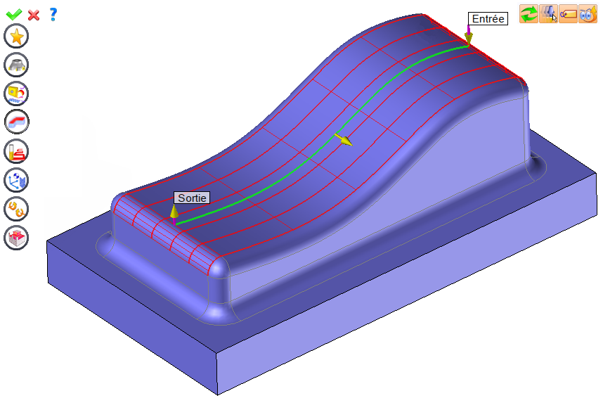
You can then modify values by
By selecting the value to modify in the label. The label is the table shown in the image in the top right corner. All label values are fields available from one of the icons in the left section. These values are placed on the label for quicker access.
By selecting the values in the graphic area or by pulling the arrows. As with the values of the labels, these fields are present in one of the left section icons. These values are placed in the graphic area for quicker access.
By opening one of the left section icons.
|
Select Favorite
Instead of modifying n values, this option allows you to restore (or save) values that have already been entered.
|
|
Select the tool to use
By default, if the previous operation tool can be used, it is reused for this operation (the name of the tool appears in the graphic area next to
If the previous tool is not suitable or if this is the first operation, you must select a tool to validate the operation (
|
|
Define Cutting Conditions for Operation
Use this icon to modify the cutting conditions of the current operation.
|
|
Define or Add Geometries to Machine
Use this icon to select (or remove) machinable geometries. This geometry is automatically added, by first selecting the geometry and right-clicking "End Milling". You do not have to access the icon to do this.
Define Milling Boundaries
You can also apply trims (XYZ or contour) to the current operation.
|
|
Define All Milling Settings
Each milling has specific settings. Use this icon to access all settings (such as stocks to leave, altitudes, plunge modes, milling modes, etc.)
|
|
Define ISO File Settings
Use this icon to define which comment to use for the ISO code or to decide which inclined plane matrices to use.
|
|
Define colinear axis
This icon is available only if the current machine has colinear axis.With this icon it will then be possible to choose the axis drives by the operation.We also can choose the Z value of the fix axis. |
|
Allow us to add one or more axis on the current machining
With this icon it is possible for example to make radial, axial machining or tilt the machining.
|
|
Define Operation Properties
Use this icon to define whether you would like to update the stock or calculate the result later.
|
|
Confirm
To confirm the current operation, pressing this icon to right-click outside the window and use the "OK" menu
|
|
Cancel
If you wish to cancel the operation, click this icon.
|
|
Preview
Display or hide the machining area. When this is hidden, this area is not calculated, and response times improve.
|
|
Show Label
Allows you to display or hide the graphic area label.
|
|
Editing Update
Each time a setting is changed (such as the axial depth), all calculations for updating the hatching area and the trajectory are triggered. The setting change may take a few moments. In several cases, settings must be modified before updating the calculations. For this, press this icon. In the case, the hatching area and trajectory (for example) are not recalculated before pressing this icon again.
|
 Click the different areas in the image below
Type of machining |
|
Time |
|
Computing Tolerance |
|
Step overs |
|
Scallop Heights |
|
Stock to Leave Constant |
|
Maximum Distance Between Points |
Visibility management when editing the operation: click on the icons below
Machine visibility |
WCS visibility |
Tool visibility |
Collision visibility |
Stock and finish visibility |
Tool paths visibility |
|
|
|
|
|
|
|
|


 )
) )
)


