Screw milling
|
Screw milling |
This is a 4 axis continuous function which allows to machine conveyor or extrusion screw kind of part.
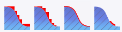
This function allows to machine on a solid or a group of surfaces.It allows to define a roughing or finishing machining by choosing in the following four machining types :
Roughing by Z cut
The left and right side of the screw are machined regardless the step over.
The tool path are smooth on the vertical side.
Few move to the safe plane.
It doesn't match when having planar areas.
 |
Roughing by Z step
The bottom of the screw is machined regardless the Z step. It is then better to use when having planar areas.
It doesn't match when having vertical areas.
 |
Finishing
The tool path correspond to "iso-parametrics"
The part machining is made with a constant scallop
 |
Material left
The aim is to machine the material left by a referenced tool. We then have to enter the reference tool in the dialog box.Only the ball nose mill are supported. we will then only ask for the diameter of the tool. After that the machining automatically machine the area which didn't being reach by the reference tool. In some critical cases it is possible to give a slightly bigger tool to bigger areas or smooth a non continuous area.
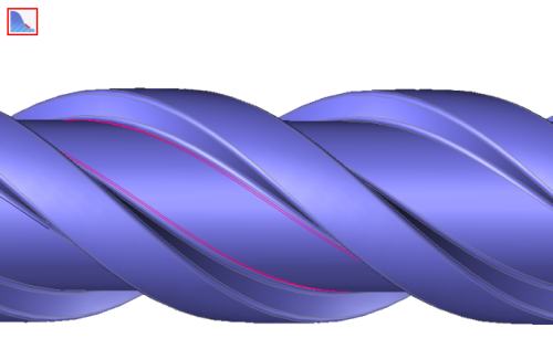 |
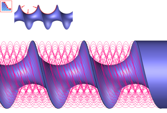
The screw machining is an operation which allows to machine screws by using two guide curves. A toolpath is then calculated between those two curves depending the kind of machining used.
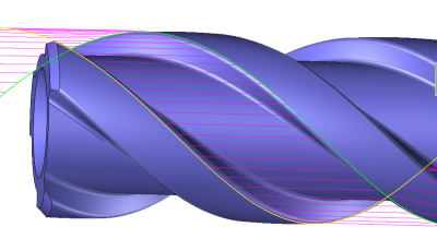
The faces that make up the model to machine are cut into radial planes containing the revolution axis of the part in order to take into account the value of the tool radius. These planes are regularly spaced at a radial pitch calculated by TopSolid'Cam. The choice of the revolution axis is essential for a smooth running of the machining.
The step over movement combines a square cycle or classic zigzag with an angular rotation of the part in order to move to the next profile.
If the rotation axis is X the tool is fix in Y and only moves along X and Z. There is an option to have the possibility to offset the tool axis refering to the revolution axis of the part.
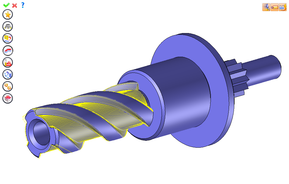
From the 4D/5D menu, select "Screw Milling...".
A toolbar appears on the left of the screen, along with a label in the graphic area.
 The topological machining isn't supported by the screw machining operation. We must select two limit curves to bound the machining.
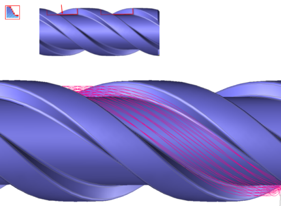
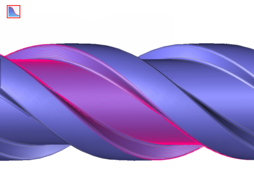
The selection order of the two curves define the machining area. A purple hatching gives a preview of this area.
 |
 |
We can then modify values by
By selecting the value to modify in the label. The label is the table shown in the image in the top right corner. All label values are fields available from one of the icons in the left section. These values are placed on the label for quicker access.
By selecting the values in the graphic area or by pulling the arrows. As with the values of the labels, these fields are present in one of the left section icons. These values are placed in the graphic area for quicker access.
By opening one of the left section icons.
|
Select a favorite
Instead of modifying n values, this option allows you to restore (or save) values that have already been entered.
|
|
Select the tool to use
By default, if the previous operation tool can be used, it is reused for this operation (the name of the tool appears in the graphic area next to
If the previous tool is not suitable or if this is the first operation, you must select a tool to validate the operation (
|
|
Define cutting conditions for operation
Use this icon to modify the cutting conditions of the current operation.
|
|
Define or add geometries to machine
Use this icon to select (or remove) the curves to limit the operation.
|
|
Define all milling settings
Each milling has specific settings. Use this icon to access all settings (such as stocks to leave, altitudes, plunge modes, milling modes, etc.)
|
|
Define ISO file settings
Use this icon to define which comment to use for the ISO code or to decide which inclined plane matrices to use.
|
|
Allow us to add one or more axis on the current machining
Use this icon to define the four axis milling settings of the screw milling operation. |
|
Define colinear axis
This icon is available only if the current machine has colinear axis.With this icon it will then be possible to choose the axis drives by the operation.We also can choose the Z value of the fix axis. |
|
Define operation properties
Use this icon to define whether you would like to update the stock or calculate the result later.
|
|
Confirm
To confirm the current operation, pressing this icon to right-click outside the window and use the "OK" menu
|
|
Cancel
If you wish to cancel the operation, click this icon.
|
|
Preview
Display or hide the machining area. When this is hidden, this area is not calculated, and response times improve.
|
|
Show Label
Allows you to display or hide the graphic area label.
|
|
Editing Update
Each time a setting is changed (such as the axial depth), all calculations for updating the hatching area and the trajectory are triggered. The setting change may take a few moments. In several cases, settings must be modified before updating the calculations. For this, press this icon. In the case, the hatching area and tool path (for example) are not recalculated before pressing this icon again.
|
 Click the different areas in the image below
Type of Machining |
|
Time |
|
Step over |
Visibility management when editing the operation: click on the icons below
Machine visibility |
WCS visibility |
Tool visibility |
Collision visibility |
Stock and finish visibility |
Tool paths visibility |
|
|
|
|
|
|


 )
) )
)