
Swept machining
|
Swept machining |
Create a tool path by running a section curve (defined in a plane orthogonal to the drive curve) on a drive curve (defined in the XY plane).
The advantage of such machining is to be able to generate as many circular interpolations as possible in the G Code.
TopSolid uses 2D machining here and not 3D.
The arcs of circles are recognized if they are present on the drive curve. The resulting tool path is therefore not only decomposed into G1 but composed of G2 or G3 which simplifies the ISO code.
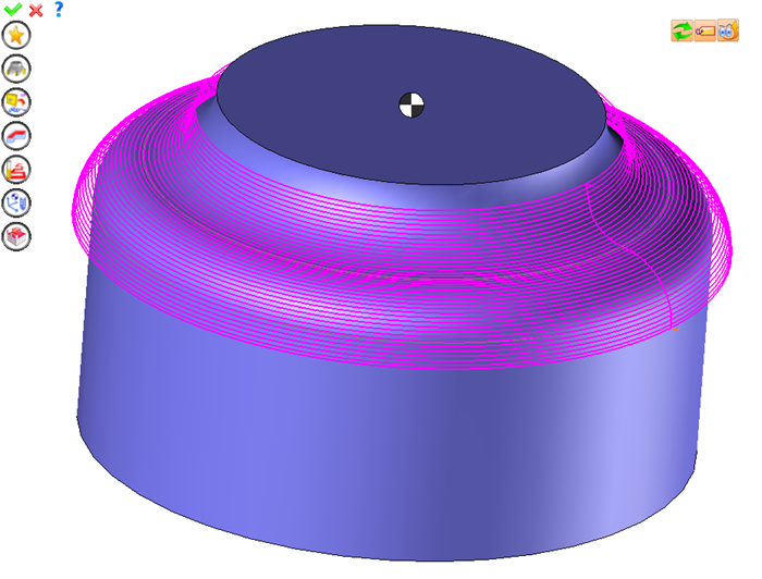
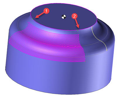
 This machining is not directly based on the part surface, simply select the two sketchs to make the machining paths.
The tool path is carried out over the entire drive curve, even if it is possible in the case of a closed drive curve to define a starting point and an end point to limit machining on a portion of the drive curve.
The machining can be done using the following tools:
- Radiused mill
- Side or slot mills
- Ball nose mill
 Undercuts on the guide curve are not supported.
Using the 2D/3D menu or a right click of the mouse select the swept machining.
A toolbar appears on the left of the screen, along with a label in the graphic area.
You can then modify values by
By selecting the value to modify in the label. The label is the table shown in the image in the top right corner. All label values are fields available from one of the icons in the left section. These values are placed on the label for quicker access.
By selecting the values in the graphic area or by pulling the arrows. As with the values of the labels, these fields are present in one of the left section icons. These values are placed in the graphic area for quicker access.
By opening one of the left section icons.
|
Select Favorite
Instead of modifying n values, this option allows you to restore (or save) values that have already been entered.
|
|
Select the tool to use
By default, if the previous operation tool can be used, it is reused for this operation (the name of the tool appears in the graphic area next to
If the previous tool is not suitable or if this is the first operation, you must select a tool to validate the operation (
|
|
Define Cutting Conditions for Operation
Use this icon to modify the cutting conditions of the current operation.
|
|
Define or Add Geometries to Machine
Use this icon to select (or remove) machinable geometries. This geometry is automatically added, by first selecting the geometry and right-clicking "End Milling". You do not have to access the icon to do this.
Define Milling Boundaries
You can also apply trims (XYZ or contour) to the current operation.
|
|
Define all milling settings
Each milling has specific settings. Use this icon to access all settings (such as stocks to leave, altitudes, plunge modes, milling modes, etc.)
|
|
Define ISO File Settings
Use this icon to define which comment to use for the ISO code or to decide which inclined plane matrices to use.
|
|
Allow us to add one or more axis on the current machining
With this icon it is possible to make radial, axial or tilt a machining.
|
|
Define colinear axis
This icon is available only if the current machine has colinear axis.With this icon it will then be possible to choose the axis drives by the operation.We also can choose the Z value of the fix axis. |
|
Define Operation Properties
Use this icon to define whether you would like to update the stock or calculate the result later.
|
|
Confirm
To confirm the current operation, pressing this icon to right-click outside the window and use the "OK" menu
|
|
Cancel
If you wish to cancel the operation, click this icon.
|
|
Preview
Display or hide the machining area. When this is hidden, this area is not calculated, and response times improve.
|
|
Show Label
Allows you to display or hide the graphic area label.
|
|
Editing Update
Each time a setting is changed (such as the axial depth), all calculations for updating the hatching area and the trajectory are triggered. The setting change may take a few moments. In several cases, settings must be modified before updating the calculations. For this, press this icon. In the case, the hatching area and tool path (for example) are not recalculated before pressing this icon again.
|
 Visibility management when editing the operation: click on the icons below
Machine visibility |
WCS visibility |
Tool visibility |
Collision visibility |
Stock and finish visibility |
Tool paths visibility |
|
|
|
|
|
|
|
|


 )
) )
)


