
Roughing
|
Roughing |
Icon Access: ![]()
Location: 2D \ Roughing
Development:
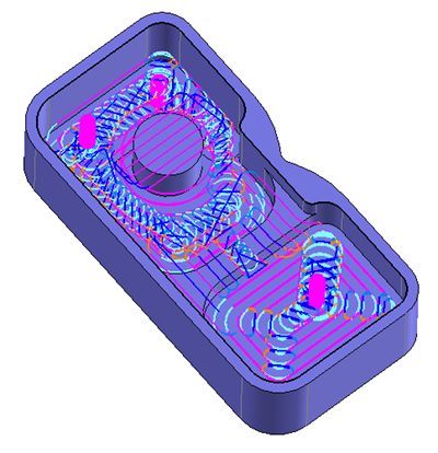
Automatically complete the roughing of a shape part using a step strategy. The operation consists of removing the most of a limited volume of the material between the shape of the rough part and the shape of the finished part.
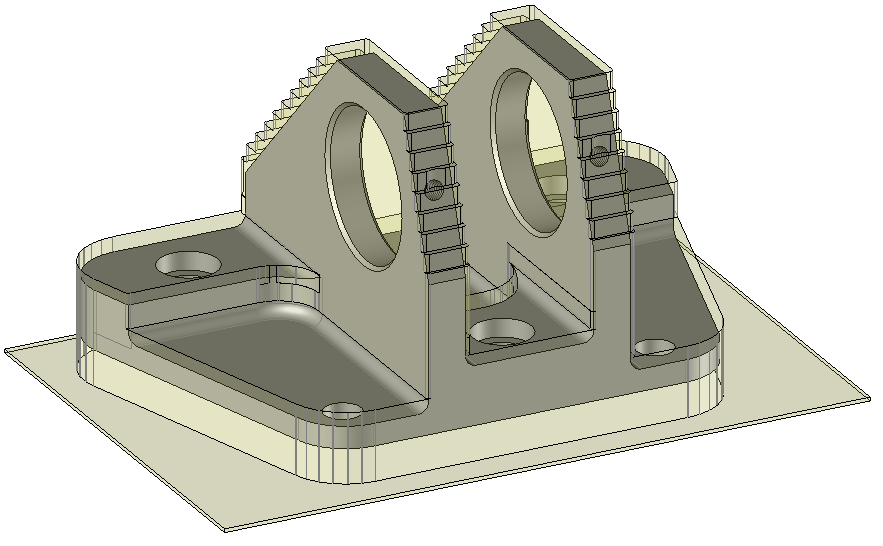
The faces that constitute the model to machine are cutted by horizontal planes, parallels to XY plane. These planes are regularly spaced by a value equal to the machining step-over (depth of each passe). These cuts are then machined by a ’2D’ machining cycle similar to the one managed by the end milling function.
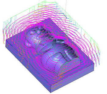
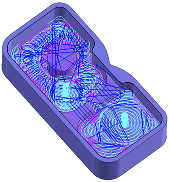
The roughing path calculation done by TopSolid'Cam takes into account the tool path from previous operations.
So it is possible to perform two roughing cycles without being forced to update the stock in order to optain a material left machining.
From the 2D/3D menu or using the mouse (by selecting or not selecting a face with the right mouse button), select the "Roughing..." menu.
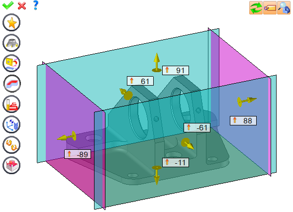
A toolbar appears on the left of the screen, along with a label in the graphic area.
There are four roughing primitives in the label.
Classical 3D roughing
This type of roughing is recommended on shaped parts such as mould cavity, electrode...
For this type of roughing radial material is preferred. It is generally recommended to not exceed a step over of 70% of the tool diameter.
 |
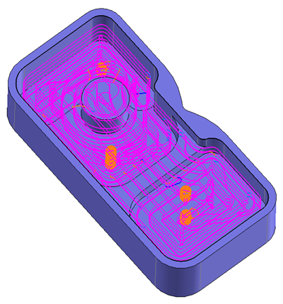
Volumill roughing (optional module Volumill) 
This type of roughing is recommended on parts with deep pockets with islands.
For this type of roughing, an important axial material is preferred and on the contrary the step over is very small.
 |
Boost roughing (optional module TopSolid) 
As for Volumill roughing this type of roughing is recommended on parts with deep pockets with islands.
For this type of roughing, an important axial material is preferred and on the contrary the step over is very small.
 |
Roughing Finishing
This type of roughing is recommended for parts with a large number of 2D operations.
In the last pass (along the finish), TopSolid tries to keep the topology of the part (radius,...).
A contouring with compensation method can be added automatically on vertical faces of the part.
For this type of roughing, an important axial material is preferred and on the contrary the step over is very small.
 |
You can then modify values by
By selecting the value to modify in the label. The label is the table shown in the image in the top right corner. All label values are fields available from one of the icons in the left section. These values are placed on the label for quicker access.
By selecting the values in the graphic area or by pulling the arrows. As with the values of the labels, these fields are present in one of the left section icons. These values are placed in the graphic area for quicker access.
By opening one of the left section icons.
|
Select Favorite
Instead of modifying n values, this option allows you to restore (or save) values that have already been entered.
|
|
Select the tool to use
By default, if the previous operation tool can be used, it is reused for this operation (the name of the tool appears in the graphic area next to
If the previous tool is not suitable or if this is the first operation, you must select a tool to validate the operation (
|
|
Define Cutting Conditions for Operation
Use this icon to modify the cutting conditions of the current operation.
|
|
Define or Add Geometries to Machine
Use this icon to select (or remove) machinable geometries. This geometry is automatically added, by first selecting the geometry and right-clicking "End c". You do not have to access the icon to do this.
Define Milling Boundaries
You can also apply trims (XYZ or contour) to the current operation.
|
|
Define All Milling Settings
Each milling has specific settings. Use this icon to access all settings (such as stocks to leave, altitudes, plunge modes, milling modes, etc.)
|
|
Define ISO File Settings
Use this icon to define which comment to use for the ISO code or to decide which inclined plane matrices to use.
|
|
Allow us to add one or more axis on the current machining
With this icon it is possible for example to make radial, axial or tilt the operation..
|
|
Define colinear axis
This icon is available only if the current machine has colinear axis.With this icon it will then be possible to choose the axis drives by the operation.We also can choose the Z value of the fix axis. |
|
Define Operation Properties
Use this icon to define whether you would like to update the stock or calculate the result later.
|
|
Confirm
To confirm the current operation, pressing this icon to right-click outside the window and use the "OK" menu
|
|
Cancel
If you wish to cancel the operation, click this icon.
|
|
Preview
Display or hide the machining area. When this is hidden, this area is not calculated, and response times improve.
|
|
Show Label
Allows you to display or hide the graphic area label.
|
|
Editing Update
Each time a setting is changed (such as the axial depth), all calculations for updating the hatching area and the trajectory are triggered. The setting change may take a few moments. In several cases, settings must be modified before updating the calculations. For this, press this icon. In the case, the hatching area and trajectory (for example) are not recalculated before pressing this icon again.
|
 Click the different areas in the image below
|
|
|
Visibility management when editing the operation: click on the icons below
Machine visibility |
WCS visibility |
Tool visibility |
Collision visibility |
Stock and finish visibility |
Tool paths visibility |
|
|
|
|
|
|
|
|


 )
) )
)


