
4 axis roughing
|
4 axis roughing |
Icon Access: 
Location: 4D/5D \ Roughing 4AX
Development:
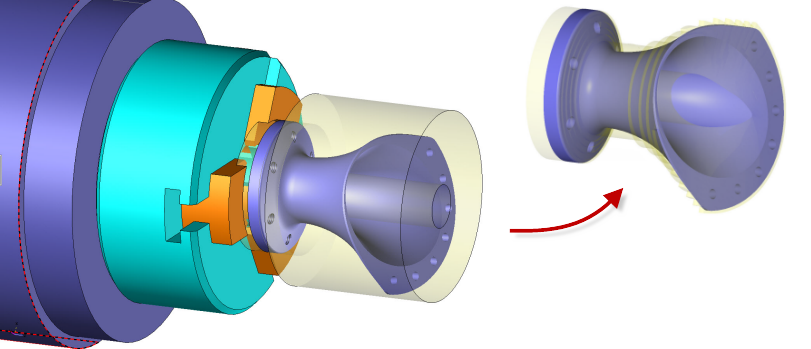
This function allows to realize automatically the 4 axes roughing of a cylindrical part.
The operation consists of removing the most of a limited volume of the material between the shape of the rough part and the shape of the finished part.
|
There are 3 strategies to realize this 4 axes roughing and the choice is made in the operation label.
The strategy using a conventional pocketing wrapped around the rotation axis of the machine.
|
4 axis radial roughing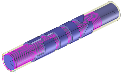 |
The strategy using a contouring of vertical faces wrapped around the rotation axis of the machine.
 |
4 axis radial roughing finishing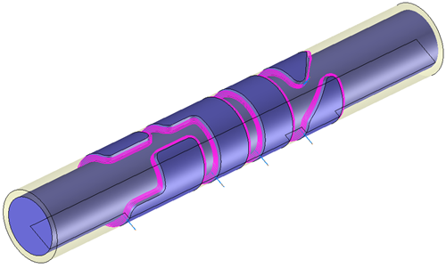 |
The faces that make up the model to mill are cut by cylinders centered on the X-axis and concentric between each other. These cylinders are spaced apart at a value equal to the milling pitch. Each cut obtained by a cylinder is "flattened", and a pocketing method is applied to it. Once the method is applied to the cut, the trajectories obtained by the cylinder are unrolled. The operation will be repeated until it exits the material.
Two important settings are the safety envelope that must surround the milling area and the driven axis that must correspond to the axis of the part.
From the 2D/3D menu or using the mouse (by selecting or not selecting a face with the right mouse button), select the "Roughing..." menu.
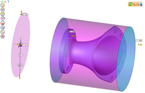
A toolbar appears on the left of the screen, along with a label in the graphic area.
|
You can then modify values by
By selecting the value to modify in the label. The label is the table shown in the image in the top right corner. All label values are fields available from one of the icons in the left section. These values are placed on the label for quicker access.
By selecting the values in the graphic area or by pulling the arrows. As with the values of the labels, these fields are present in one of the left section icons. These values are placed in the graphic area for quicker access.
By opening one of the left section icons.
|
Select Favorite
Instead of modifying n values, this option allows you to restore (or save) values that have already been entered.
|
|
Select the tool to use
By default, if the previous operation tool can be used, it is reused for this operation (the name of the tool appears in the graphic area next to
If the previous tool is not suitable or if this is the first operation, you must select a tool to validate the operation (
|
|
Define Cutting Conditions for Operation
Use this icon to modify the cutting conditions of the current operation.
|
|
Define or Add Geometries to Machine
Use this icon to select (or remove) machinable geometries. This geometry is automatically added, by first selecting the geometry and right-clicking "End Milling". You do not have to access the icon to do this.
Define Milling Boundaries
You can also apply trims (XYZ or contour) to the current operation.
|
|
Define All Milling Settings
Each milling has specific settings. Use this icon to access all settings (such as stocks to leave, altitudes, plunge modes, milling modes, etc.)
|
|
Define ISO File Settings
Use this icon to define which comment to use for the ISO code or to decide which inclined plane matrices to use.
|
|
Define colinear axis
This icon is available only if the current machine has colinear axis.With this icon it will then be possible to choose the axis drives by the operation.We also can choose the Z value of the fix axis. |
|
Define Operation Properties
Use this icon to define whether you would like to update the stock or calculate the result later.
|
|
Confirm
To confirm the current operation, pressing this icon to right-click outside the window and use the "OK" menu
|
|
Cancel
If you wish to cancel the operation, click this icon.
|
|
Preview
Display or hide the machining area. When this is hidden, this area is not calculated, and response times improve.
|
|
Show Label
Allows you to display or hide the graphic area label.
|
|
Editing Update
Each time a setting is changed (such as the axial depth), all calculations for updating the hatching area and the trajectory are triggered. The setting change may take a few moments. In several cases, settings must be modified before updating the calculations. For this, press this icon. In the case, the hatching area and trajectory (for example) are not recalculated before pressing this icon again.
|
 Click the different areas in the image below
|
|
| 0.1 | |
| Yes |
Visibility management when editing the operation: click on the icons below
Machine visibility |
WCS visibility |
Tool visibility |
Collision visibility |
Stock and finish visibility |
Tool paths visibility |
|
|
|
|
|
|
|
|


 )
) )
)


