
List of Tools in Carousel
|
List of Tools in Carousel |
This table groups the document tools used in the carousel.
|
Pocket Axis |
Description |
D |
L |
|
|
|
1 |
Z+ |
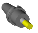
Mill to Face with D63 A0 L5 SD41 Extension |
63mm |
5mm |
|
|
2 |
Z+ |
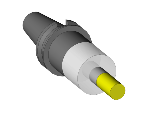
Side Mill D20 L35 SD20 Extension |
20mm |
35mm |
|
|
3 |
Z+ |
|
|
|
|
|
4 |
Z+ |
|
|
|
|
|
5 |
Z+ |
|
|
|
|
|
6 |
Z+ |
|
|
|
|
|
7 |
Z+ |
|
|
|
|
|
8 |
Z+ |
|
|
|
|
|
9 |
Z+ |
|
|
|
|
|
10 |
Z+ |
|
|
|
To add a tool to the carousel (in order to use it), there are two solutions:
 Allows to access to a generic tools database and then to add a tool.
A window appears with many tabs:
The Component(s) tab allows to define the geometrical characteristics of the cutting part (and the extension and the cone) as the tool diameter, the cutting length, the shank diameter...
The number of tool parameters depends on its shape.
Component(s) Description Side Mill D20 L35 SD20 Extension
Component(s) Template(s) Info. Tool assembly
|
Several additionnal parameters can be accessed by clicking on the advanced button as the tool teeth number, the cutting part material or if the tool has a coolant nozzle...
Advanced parameters
Number of Tool Teeth Cutting Tool Material Coated carbide Left Tool Coolant Nozzle Maximum Plunge Angle
|
The Template(s) tab allows to choose from a type of assembly.For example it is possible to define if the tool has an extension or if it is fretted tool...
 |
 |
 |
Depending on the chosen model, some additional parametrised components allow to define the generic tool dimensions.


 It is possible to configure the default model by clicking on the fixed favors button.
The tab "Info" allows to resume the tool caracteristics.
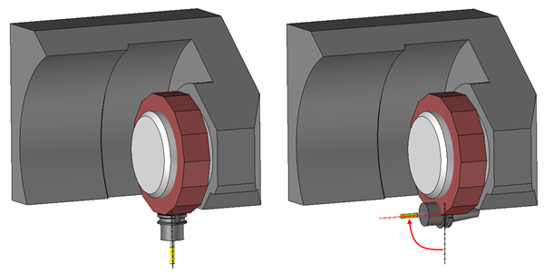
The tab "Tool assembly" allows to define the position and the orientation related to the tool holder.
For example, you can define :
Output distance
(This option allows to set the tool components position according to the chosen articulation.For example it allows to set output distance.
 |
- An indexation angle in the tool holder.
(This option allows to rotate the tool around the tool holder axis (for example to do a left or right machining in turning).
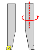 |
- An orientation angle in the tool holder
(This one is very important to orientate the tool on a turret to do axial operations or operations on sub-spindle).
 |
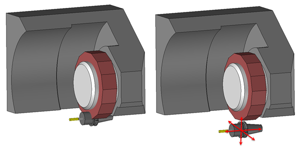
- An offset along X,Y or Z axes related to the pocket.
 |
The tool number will be the first free number.To set a number, just double-click the type of tool to select the line that corresponds to the pocket number.
Before to validate a tool it is possible to give it a name in the description field.
If the field is grayed out then the tool (with the actual definition) already exists in the library « TopSolid Machining user Tools ».
 Allows to access to itsown databases and then to add a tool.
A dialog box appears to select a tool in the catalog.
Catalog Description Cutting Diameter Cutting Length Cutting Tool Material Category |
By default, a filter is applied to limit the proposed tool list.For example this filter allows to only display tools with a compatible attachment with the machine.
To hide or show the filter just click on the icon: 
Catalog filter Operation filter
Description:
Tooling system:
Helical Drill |
 |
This option allows to filter the tool catalog according to the selected geometry in the machining operation.For example with a drilling a filter is applied according to hole diameter and depth. |
 |
Below the option Operation filter are displayed the filters used by TopSolid to filter the catalog according to the selected geometry and operation.(They are not modifiable) |
 |
|
 |
Tooling system
It is possible to apply a filter on the attachment. By default the filter is automatically given by the tool holder of the machine. |
 |
Tool parameters Finally it is possible to filter the tool list by imposing custom dimensions.
|
 This icon allows to select the project or library in which the tool will be chosen.
 This icon allows to open the file which contains the assembled tool.It is in read only and we leave the current function.
It is also possible to access to commercial databases ( Adveon, TDM, Machining Cloud, ....)
In this case additional icons may appear to import these tool libraries. For example:
 This icon allows to import tools in the library defined in the "Machining Cloud" in Tools / Options.
Simply specify the folder that contains compressed files exported from "Machining Cloud".
Tool Manager
Project name
Export sub folders |
The tool number will be the first free number.To set a number, just double-click on the line that corresponds to the pocket number.
Checkbox:
|
This is the active tool that we will use.We can therefore edit and use it for the current milling. The tool is displayed at the end of the cursor in the work area depending on the orientation of the current operation. |
|
|
|
The tool is not active; it exists in the carousel but will not be used for this milling operation. |
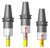
This is the location number of the tool in the carousel.
Pocket Axis
Indicates the axis that the tool will ascend.
These axes are defined when the machine (tool holder) is created.
Here, you can only use them to see whether the tool went up a turret on the X+ axis (perpendicular to Z axis) or the Z+ axis (parallel to Z axis).
Description
Tool Name
Diameter
Cutting Part Diameter of the Tool
Length
Cutting part length of the tool
To show other tool characteristics just do a right click on the tool list and choose the customize option.
 Click the different areas in the image below
|
New tool from catalog Ctrl+ Shift+Insert Sort tools in the order of machining Reload tool cutting conditions |
|
Information / Tips
The choice for the catalog tools will be limited bu default to this list.
- Just click on The check mark in front of each library or project mans that the tools will be preloaded in memory at the start of the TopSolid session. .
- However it will be possible to choose tools outside the preloaded list by switching the button
|


 or directly from the "Operations Manager", also by a double-clicking.
 expands the list to all the tools of the same family.
 Only tools of the short list are guaranteed to work with the algorithm of the current operation.
 to add a library.
 during a search for a tool in the catalog.