
WCS and origins manager
|
|
WCS and origins manager |
This is the dashboard for origins and WCS.
We will then be able to quickly change a WCS (application point for example) or an origin (application point or origin number). It will also be possible to create new origins and WCS or delete the ones which are not use.
|
|||||||||||||||||||||||||||||||||||||||||||||||||||||||||||||||||||||||||||||||||||||||||||||||||||||||||||||||
 Localisation of the elements from the WCS and origins manager:
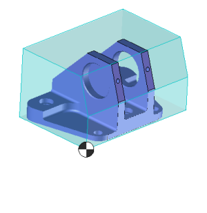 |
When we click in the WCS and origins manager on a machined part it becomes blue in the graphical area
|
|
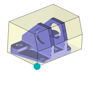 |
When we click in the WCS and origins manager on a WCS or an origin it becomes blue in the graphical area
|
|
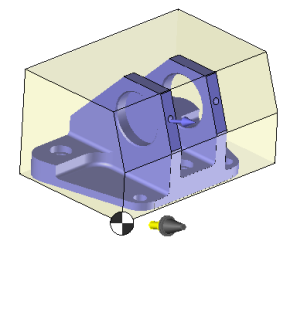 |
When we click in the WCS and origins manager on a WCS, a tool which shows the orientation of the WCS appears in the graphical area.
|
|
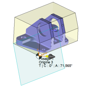 |
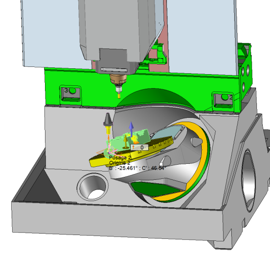
When we click in the WCS and origins manager on a WCS solution, a tool which shows the orientation of the WCS appears in the graphical area. A blue plane (machining plane) also appears to show us the selected angular solution and an orange frame shows the axes orientation of this plane.
|
Possible actions:
|
|
Search
This search allows to automatically open the nodes refering to the syntax we wrote (We can then quickly identify by the name an origin or a WCS) |
|
|
Number of elements
This option allow to show the number of elements in each node. |
|
|
Add from face
This allows to create a WCS from a face. |
|
|
Add from frame
This allows to create a WCS from a frame. |
|
|
Edit
Edit the selected WCS in order to modify all the parameters. |
|
|
Delete
Delete the selected WCS |
|
|
Delete the unused WCS
Delete all the unused WCS of the cam document. |
|
|
Optimize origins and WCS
As indicated above, by automatically moving the WCS and origins as low as possible in the creation history, they become accessible to all cam operations.
|
|
|
Attached all the solution frame to the origin
This position the application point of all the WCS on the part origin |
|
|
Attached all the frames in the center of the geometry used to define its.
This position the application point of all the WCS on the center of the selected face for the machining. |
|
Only show the used solutions. |
Only show the used solutions.
Only show the solutions used by an operation. The others will be hided. |
|
Show normalized rotation |
Show normalized rotation
Concerning the machine with axis that are not colinear to the XYZ frame of the machine (DMU Evolinear for example) there are two different ways to calculate the rotation angle:
For example our machine has a table which is inclined by 36.5°. The resulting rotation angle in order to reach an inclined face of 20 ° won't be 20° if we are ppositioned on this rotation axis.In order to get the 20° we must be positioned on the normalized frame XYZ of the machine.This is what this box has been made for.
The face to machine is oriented from 20° from the table. Without showing the normalized rotation we will have values like B : -25.461° and C : 46.54°. If the normalized rotations are actives we will have much more comprehensive values refering to the part like B : 20°
|
|
|
Confirm
To validate the change simply click on this icon or right click outside the window and choose "OK" in the menu.
|
|
|
Cancel
To cancel this operation simply click on this icon or right click outside the window and select "cancel" in the menu. |
From the tab Operation select the menu WCS and origin manager.
 |
TopSolid allows the multiple selection by using the "CTRL" or "MAJ" keys in the WCS and origins manager:
- It is possible to select several WCS to delete them with the icon - It is possible to drag several WCS on an origin in order to modify them. |


 Any change will make the existing operations that used one of the modified WCS or origin to be reexecuted.
 .
.