Create from frame
|
Create from frame |
This step is not essential.By default if the WCS doesn't exist when creating the operation TopSolid will create it automatically.
This step can be useful to get information about the machine strokes needed to reach or not a frame without creating a machining operation.If we can't reach the frame we must then change the part positioning or the machine.
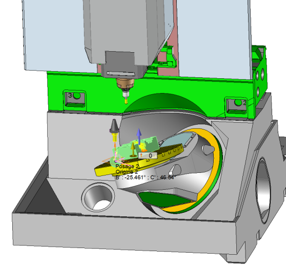
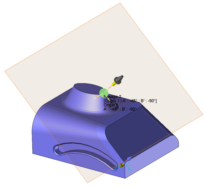
If we can reach the frame with the machine strokes TopSolid calculates automatically the values of the machine axis to position the part (numerical values on the picture). A small tool representation appears to visualize in which direction the tool will be oriented.
Create from a frame
Frame
Frame1
Tool holder
Spindle
Part
Part 1
WCS
Description
[Origin 1 | A' : 45° ; B' : 0°]
Origin
Iso bloc origin :
Origin 1
Frame associated to the current solution :
Frame 2
Inclined plane matrix activated
Solutions
Show normalized rotation
Show machine in position |
Frame Frame to use. |
Tool Holders Allow to know which machine axis will be used. |
Part Allow to identify the part holder (for example on a turning machine to indicate if we are on the main or sub spindle). |
Description Information about WCS. This comment may appears in the ISO file.You can therefore modify itBy default TopSolid indicates according to which origin the WCS is linked and also the angular values of the machine axis. |
Iso bloc origin Part origin. This is refering to this origin that the Iso code will be calculated. |
Frame associated the the current solution This frame is a local origin which in most of the case is coinciding with the part origin.It could be used to realize an origin offset or call a matrix plane for example. |
|
Inclined plane matrix activated (box ticken the iso code will put an Iso function like G68.5 to activate this new WCS). |
|
Show normalized rotation As indicated below if the rotation angles are not parallel to the X, Y or Z axis of the machine this checkbox allows to decide which angle we want to see in the list. |
Solutions The solutions are the result of the different possibilities of the machine axis found between the tool holder and the part.TopSolid cannot calculate in automatic all the solutions. TopSolid stops on the main solutions. It is then possible to add solutions as indicated below. The list shows us all these solutions |
|
Allow to show the machine in position. We can then see the machine with all the axis oriented.
|
|
TopSolid asks for an automatic solution as soon as the select element is usable.. But in the case where we have several solutions or if we need a specific solution it is useful to be able to modify the WCS. |
|
|
Add a value
This button allows you to define an additional customized solution to reach the WCS. |
|
Remove a value
This function allows us to delete the selected solution. |
Example of normalized rotations
|
If our machine has a table with an inclined position at 36.5°. The resulting rotation angle in order to reach an inclined face of 20 ° won't be 20° if we are ppositioned on this rotation axis. In order to get the 20° we must be positioned on the normalized frame XYZ of the machine.This is what this box has been made for. The face to machine is oriented from 20° from the table. Without showing the normalized rotation we will have value like B : -25.461° and C : 46.54°.
If the normalized rotations are actives we will have much more comprehensive values refering to the part like B : 20° |
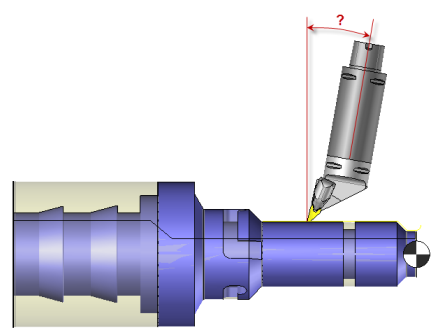
User solution in turning on a machine with with a B axis programable on the tool holder
|
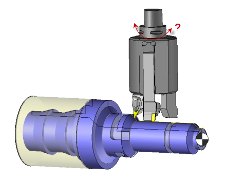
User solution in turning on a machine with with a A axis programable on the tool holder
|
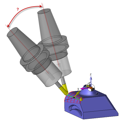
Solution in milling with a B axis
|
|
|
|
From the operation tab select create from a frame. This function is also accesible from the operation on the WCS area.
 The box that displays the machine in position cannot be accessed to simulate the machine orientation in the case of a virtual machine.