Part 1


Side Mill

A° C°

Surfacing
|


Shape 1
|
Simulation / Verification |
To better view the operation(s), TopSolid proposes two options with proper representation modes.
They can be accessed from the right-click menu on the operation we want to verify or the part in order to verify all operations, or from the Verification tab:
|
|
Part 1 |
|
|||||||||||||||||||||||||||||||||||||||||||||||||||||||||||||||||||||||||
|---|---|---|---|---|---|---|---|---|---|---|---|---|---|---|---|---|---|---|---|---|---|---|---|---|---|---|---|---|---|---|---|---|---|---|---|---|---|---|---|---|---|---|---|---|---|---|---|---|---|---|---|---|---|---|---|---|---|---|---|---|---|---|---|---|---|---|---|---|---|---|---|---|---|---|---|---|
|
|
|
Side Mill |
|
||||||||||||||||||||||||||||||||||||||||||||||||||||||||||||||||||||||||
|
|
|
|
A° C° |
|
|||||||||||||||||||||||||||||||||||||||||||||||||||||||||||||||||||||||
|
|
|
|
|
Surfacing |
|
||||||||||||||||||||||||||||||||||||||||||||||||||||||||||||||||||||||
|
|
|
|
|
|
Shape 1 |
||||||||||||||||||||||||||||||||||||||||||||||||||||||||||||||||||||||
|
|
|
|
|
|
|
|
|
||||||||||||||||||||||||||||||||||||||||||||||||||||||||||||||||||||
Simulation Mode:
Several options are proposed in this mode:
Material Removal
|
With Material Removal |
|
Without Removing Material |
Simulation Mode
|
The programming simulation mode where only the tool is represented. |
|
Simulation Mode, such as on the machine. |
Display options
|
The option Erase tool path display (if we asked to see all the tool path in the simulation options) allows to erase the display of the already done tool path and so we will only see the tool path since the current position. |
|
Allows to show / hide origins during the simulation. |
|
This option is available only in machine simulation mode.It allows to see the power axes rotation in the simulation. We can visualize : Part rotation in turning operations, Tool rotation (with Andrea head) |
Tool display options
During the simulation in programmation mode  it is possible to select the tool elements to visualize by clicking on the icon black arrow
  .
.
|
|
|
|
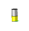
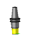
It is also possible to show the tool in wireframe, semi-transparent or opaque render.
 |
 |
Others display options
|
Simulate with time increment. The simulation speed is proportional to the feed rate of the operation. |
|
Simulate with length increment. The simulation speed is constant.It does not depend on the feed rate of the operation. |
|
A right click on the simulation window allows to personalize it. It is possible to adjust the font size, the decimal digits and to display the following informations :
|
|||||||||||||||||||||||||||||||||||||||||||||||||||||||||||||||||
Verification Mode:
In the verification mode we can choose between machine simulation mode or programming simulation mode.
|
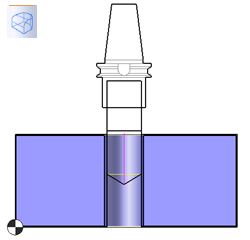
Programming simulation mode When this simulation mode is active we simulate the operations only with the tool.
|
|
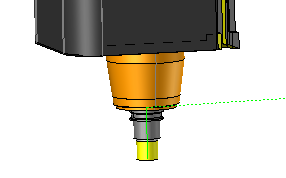
Machine simulation mode When this simulation mode is active we simulate the operation with the tool and the machine. The command "Display static tool " is so not taken into account in machine mode.
|
|
When this option is active we detects the collisions. |
|
Start in Turbo Mode This option allows to directly display the material removal result in a Z buffer view. It is only accessible when millings sharing the same WCS are verified.
|
|
Start in Animation Mode You can view the animation of the tool that removes the material following the set trajectories. This mode allows you to view millings having various WCSs. However, the calculations are more cumbersome and therefore take more time.
|
In the simulation:
Several sliders appear to adjust the speed and position of the simulation:
Simulation position |
When there are several operations selected for simulation, this cursor allows to move through the machining range from operation to operation.
 represents the beginning of the machining range and
  represents the end of the machining range.
Operation position |
When an operation is long this cursor allows to move on the tool path of the operation being simulated.
represents the beginning of the tool path and represents the end of the tool path.
Simulation Speed |
This slider is used to set the overall speed during the simulation.
represents the minimum speed and represents the maximum speed.
.
Power axis simulation speed |
This slider is used to set the simulation speed of the power axes.
represents the minimum speed and represents the maximum speed.
Speed coefficient for rapid movements |
This slider is used to set the simulation speed of the rapid movements. It is a coefficient in relation to the value of the rapid feed rate defined in the machine.
allows to reduce the speed of the movements in rapid to the maximum and allows to return to the value set in the machine for rapid feed rate.
This last cursor is only accessible with the time-based simulation.  .
.
In the verification:
When the verification calculation is finished, we can perform a comparison  using the right-click menu or Verification tab to check the difference between the verification result and the Design part.


 Cutting edge