X or Y (depending the rotation axis of the machine) maximum/minimum does not define the machining boundings but the limit of the meshing (which will be use to land the tool).
This value allows to define the area on which the meshing of the function will be done to calculate the tool path.
X or Y (depending the rotation axis of the machine) maximum/minimum does not define the machining boundings but the limit of the meshing (which will be use to land the tool).
By default the meshing area corresponds to the area on which the tool path will be created. But in some cases it is possible to increase it to avoid direction changes on the sides (to respect the part border the tool path tool path may evolve towards a point of this one)
|
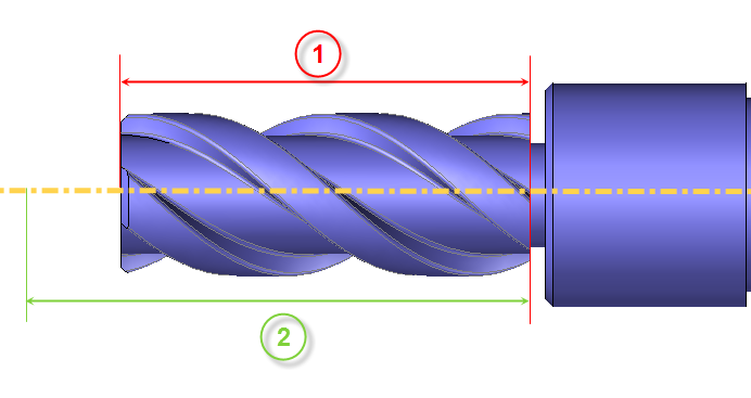
In the following example the area (1) defines the area where the tool path will be created and the area (2) the meshing zone of the function. |
|
|
|
|
|
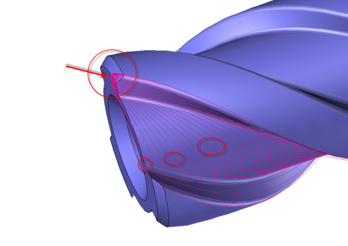
When the area (2) of the meshing and the area (1) are the same we have a direction change of the tool path. |
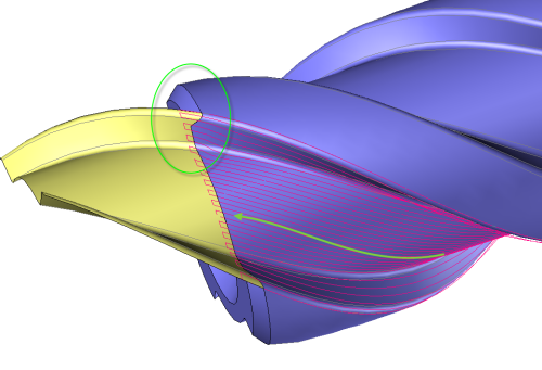
When the area (2) of the meshing is bigger than the area (1) the tool path stay "constant".
|
 |
 |