
TSlot milling
|
TSlot milling |
To realize :
- Lateral slots along a part.TopSolid recommands a number of pass in Z refering to the height of the slot, the cutting length of the tool and the cutting conditions
- Back contouring.
With this function we can machine lateral slot without repositioning the part.We can then improve the quality of the machining and win time.
The aim of this function is to remove all the material along a vertical face by using an open or closed profile between two horizontal faces of the finish part.
|
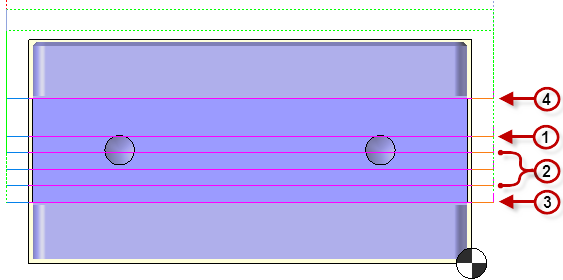
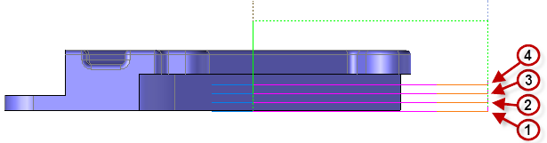
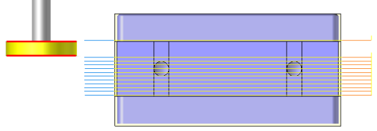
TopSolid realizes the Tslot operation by making first a central tool path and then upper and lower tool path. We can then have a precise machining by using the appropriate bottom or top tool offset.The path order will be as following :
|
|
Doesn't matter the driven point used, the first path is always made at the lower Z of the vertical profile or face. Then, the tool will go up in Z+ of the axial depth until it will finish the vertical face of the part. The path order will be as following :
|
The Tslot milling cycle processes simple and complex contour faces. Corners with a radius less than the tool radius do not interfere in any way with the calculation of the tool path. In this case TopSolid generates residual material that may be machined later.
It is possible to use the Tslot milling by selecting the vertical face at the bottom of the slot and then use the topological mode, or by using one of the four profiles in the list below to use the "wire" mode.
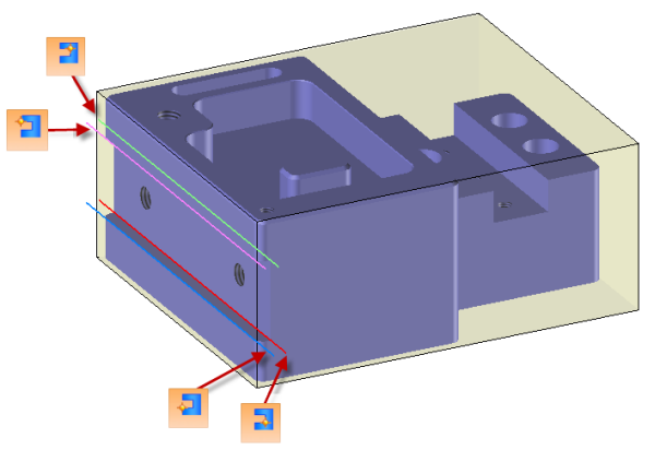
If a profile has been selected instead of the vertical face we must then define the material side and the slot characteristics (height and depth).
In order to define the tool offset we have to go in the cutting conditions panel and then in the gauges tab ,
,
The tool path calculation automatically manages the tool offset change when it is necessary (2 offset selected).
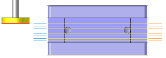
Tool path using the bottom tool offset |
|
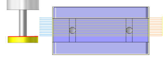
Tool path using the top tool offset |
|
Tool path using 2 offsets (Change of corrector on the upper face of the slot in order to keep a precise dimension on the width) |
|
 Only T slot mill are supported with this function.
We can then modify values by
Selecting the value to modify in the label. The label is the table shown in the image in the top right corner. All label values are fields available from one of the icons in the left section. These values are placed on the label for quick access.
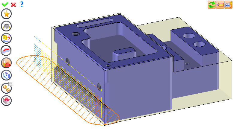
Selecting the values in the graphic area or by pulling the arrows (the 2 fields have a value of 0.5 in the top image, above the hatching area). Like the values of the labels, these fields are present in one of the left section icons. These values are placed in the graphic area for a quick access.
Opening one of the left section icons.
|
Select Favorite
Instead of modifying n values, this option allows you to restore (or save) values that have already been entered.
|
|
Select the tool to use
By default, if the previous operation tool can be used, it is reused for this operation (the name of the tool appears in the graphic area next to
If the previous tool is not suitable or if this is the first operation, you must select a tool to validate the operation (
|
|
Define cutting conditions of the operation
Use this icon to modify the cutting conditions of the current operation.
|
|
Define or add geometries to machine
Use this icon to select (or remove) machinable geometries. This geometry is automatically added, by first selecting the geometry and right-clicking "End Milling". You do not have to access the icon to do this.
Define milling boundaries
You can also apply trims (XYZ or contour) to the current operation.
|
|
Define all milling settings
Each milling has specific settings. Use this icon to access all settings (such as stocks to leave, altitudes, plunge modes, milling modes, etc.)
|
|
Define ISO File Settings
Use this icon to define which comment to use for the ISO code or to decide which inclined plane matrices to use.
|
|
Define colinear axis
This icon is available only if the current machine has colinear axis.With this icon it will then be possible to choose the axis drives by the operation.We also can choose the Z value of the fix axis. |
|
Allow us to add one or more axis on the current machining For example on 4 and 5 axis machine, to have the possibility of doing radial or axial operations. |
|
Define operation properties
Use this icon to define whether you would like to update the stock or calculate the result later.
|
|
Confirm
To confirm the current operation, press this icon right-click outside the window and use the "OK" menu
|
|
Cancel
If you wish to cancel the operation, click this icon.
|
|
Preview
Display or hide the machining area. When this is hidden, this area is not calculated, and response times improve.
|
|
Show Label
Allows you to display or hide the graphic area label.
|
|
Automatic edit refresh
Each time a setting is changed (such as the axial depth), all calculations for updating the hatching area and the trajectory are triggered. The setting change may take a few moments. In several cases, settings must be modified before updating the calculations. For this, press this icon. In the case, the hatching area and trajectory (for example) are not recalculated before pressing this icon again.
|
 Click the different areas in the image below
#1 |
|
Altitude... |
|
Stock to leave on floor |
0.5mm |
Stock to leave on side |
0.3mm |
Side stock to leave on islands |
1mm |
Maximum Axial Depth |
5mm |
Final Axial Depth |
0mm |
|
|
Tool path preview |
Visibility management when editing the operation: click on the icons below
Machine visibility |
WCS visibility |
Tool visibility |
Collision visibility |
Stock and finish visibility |
Tool paths visibility |
|
|
|
|
|
|
|
|
 Tslot milling : Simple
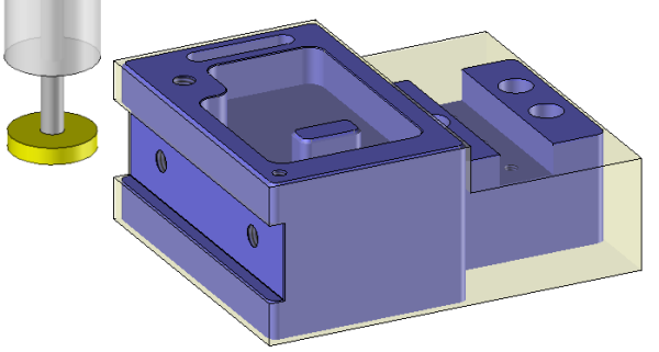
 T slot milling : Back machining
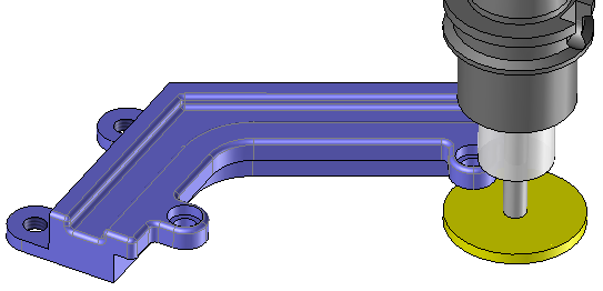


 )
) )
)


